OPNsense Home Lab Walkthrough: Segmented VLANs, WireGuard, Suricata IPS, Zenarmor, and Centralized DNS
OPNsense Home Lab Walkthrough: Segmented VLANs, WireGuard, Suricata IPS, Zenarmor, and Centralized DNS
Overview
This post documents a security-focused home lab built around OPNsense as the routing, firewall, VPN, and inspection platform. The design uses VLAN segmentation, dedicated security infrastructure, centralized DNS enforcement, layered network inspection, and a dedicated Ubuntu-based security stack running containerized SIEM, threat intelligence, and DNS tools.
This walkthrough covers the full build from hardware selection through final validation, including:
- preparing your ISP router for bridge mode
- installing and configuring OPNsense on a Protectli appliance
- configuring a Netgear managed switch for 802.1Q VLAN segmentation
- building an Ubuntu Server security stack
- deploying AdGuard, Wazuh, and OpenCTI in Docker
- enabling Suricata IPS and Zenarmor on OPNsense
- WireGuard remote access
- DNS enforcement and firewall policy by zone
Related Add-On Writeups
- DShield Honeypot Add-On for the OPNsense Homelab
- Wazuh with Docker: Standalone Setup for Agents, Log Aggregation, Alerts, and Notifications
- OpenCTI with Docker: Standalone Setup for Threat Intelligence and IOC Workflows
- AdGuard with Docker: Standalone Setup and DNS Enforcement Validation
Design Principles
- Default-deny mindset: internal access between networks is allowed only where explicitly needed
- Management isolation: infrastructure administration is not broadly reachable
- DNS consolidation: all client DNS flows through an approved internal resolver
- Layered inspection: perimeter IPS and internal VLAN analytics complement each other
- Containment over convenience: lab, IoT, guest, and honeypot traffic is never implicitly trusted
- Sanitized documentation: management addresses and operational specifics are not published publicly
Hardware Used in This Build
Firewall: Protectli VP2420
The Protectli VP2420 (or equivalent 4-port fanless x86 appliance) is the recommended platform for this build.
| Spec | Detail |
|---|---|
| CPU | Intel Celeron J6413 quad-core (or N100/J6412-class) |
| RAM | 8 GB DDR4 minimum; 16 GB recommended for Suricata and Zenarmor |
| Storage | 32 GB eMMC minimum; 64 GB mSATA or M.2 SSD recommended |
| NICs | 4x Intel i225/i226 2.5GbE |
| Form factor | Fanless, wall-mount or rack-shelf capable |
Why Intel NICs matter: OPNsense, Suricata, and Zenarmor all have better driver support and hardware offload compatibility with Intel i225/i226 NICs than Realtek-based appliances. Avoid Realtek-based devices for inline IPS workloads.
If you need more physical ports, the VP4630 (6-port) or VP6630 (6-port with SFP) are suitable upgrades from the same product line.
Managed Switch: Netgear GS308E or GS324T
| Model | Ports | Notes |
|---|---|---|
| GS308E | 8x 1GbE | Suitable for small labs, web-managed, low cost |
| GS316EP | 16x 1GbE PoE | Good if you have wireless APs or PoE cameras |
| GS324T | 24x 1GbE | Better for larger builds; supports static routing |
All three models support 802.1Q VLAN tagging, which is required for this architecture.
Security Stack Server
Any x86 machine with enough resources works. Suggested specifications:
| Spec | Minimum | Recommended |
|---|---|---|
| CPU | Dual-core x86-64 | Quad-core or better |
| RAM | 8 GB | 16 to 32 GB (Wazuh indexer is memory-hungry) |
| Storage | 128 GB SSD | 500 GB or more SSD (log storage fills fast) |
| NIC | 1x Gigabit Ethernet | 1x Ethernet, connected to igc2 on the Protectli |
Small form-factor options that work well: Beelink EQ12 or SER5, Intel NUC 10/11/12, or a repurposed office mini-PC.
ISP Router / Modem
Most ISP-provided modem-routers support bridge mode or IP passthrough. You do not need to replace the ISP device. The key step covered in Phase 0 is configuring it correctly before you deploy OPNsense.
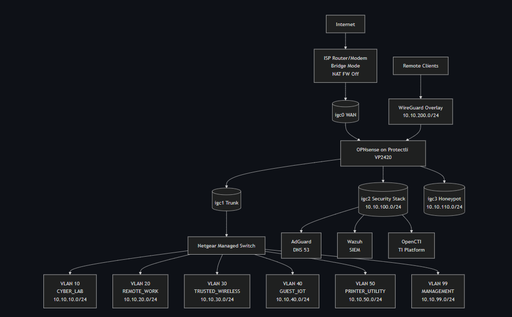
High-Level Topology
1
2
3
4
5
6
7
8
9
10
11
12
13
14
15
16
17
18
19
20
21
22
23
24
25
26
27
28
29
30
                    Internet
                       |
                 ISP Router/Modem
                 (bridge mode, NAT firewall off)
                 Management fallback: 192.168.100.1 direct LAN port
                       |
                    [ WAN ]
                     igc0
                       |
              +--------------------+
              |     OPNsense       |
              |   Protectli VP2420 |
              |--------------------|
              | igc1 -> VLAN trunk -> Netgear Switch
              | igc2 -> Security Stack (10.10.100.0/24)
              | igc3 -> Honeypot (10.10.110.0/24)
              +--------------------+
                       |
                 Netgear Switch
                       |
     -------------------------------------------------
     |         |            |          |       |      |
   VLAN10    VLAN20       VLAN30     VLAN40  VLAN50 VLAN99
   Lab       Remote Work  Trusted    Guest/  Printer Mgmt
                          Wireless   IoT

  Ubuntu Security Stack (igc2, 10.10.100.10):
    - AdGuard Home   (port 53, 80, 443)
    - Wazuh SIEM     (port 443)
    - OpenCTI        (port 8080)
Visual Topology Diagram
Network Segmentation Model
Security Zones
| Zone | Purpose | Trust Level |
|---|---|---|
| Management | Firewall, switch, and infrastructure admin | Highest |
| Remote Work | Work endpoints and sensitive productivity | High |
| Trusted Wireless | Personal trusted endpoints over Wi-Fi | High |
| Cyber Lab | Security testing, VMs, attack simulation | Medium / controlled |
| Printer / Utility | Printers and shared devices | Restricted |
| Guest / IoT | Guest clients and smart home devices | Low |
| Security Stack | SIEM, threat intel, DNS, investigation tools | Restricted / special-purpose |
| Honeypot | Controlled exposure and telemetry | Untrusted |
| WireGuard | Remote-access overlay | Conditional |
VLAN Layout (Example — use your own addressing)
| VLAN ID | Name | Example Subnet | Notes |
|---|---|---|---|
| 10 | CYBER_LAB | 10.10.10.0/24 | Testing, VMs, offensive tooling |
| 20 | REMOTE_WORK | 10.10.20.0/24 | Business-use workstations |
| 30 | TRUSTED_WIRELESS | 10.10.30.0/24 | Personal trusted wireless endpoints |
| 40 | GUEST_IOT | 10.10.40.0/24 | Guest clients and IoT devices |
| 50 | PRINTER_UTILITY | 10.10.50.0/24 | Printers and shared devices |
| 99 | MANAGEMENT | 10.10.99.0/24 | Firewall, switch, and admin plane |
Dedicated Physical Segments
| Interface | Name | Example Subnet | Purpose |
|---|---|---|---|
igc2 | SECURITY_STACK | 10.10.100.0/24 | SIEM, AdGuard, OpenCTI, Wazuh |
igc3 | HONEYPOT | 10.10.110.0/24 | Isolated honeypot or DShield collector |
Build Order
Follow this sequence to avoid lockouts and circular dependencies:
- Prepare ISP router: disable software firewall, then enable bridge mode, preserve WebGUI access.
- Flash and install OPNsense on the Protectli.
- Assign interfaces and set initial LAN IP for web access.
- Create VLANs and assign all interfaces.
- Configure the Netgear switch trunk and access ports.
- Enable DHCP per zone.
- Apply baseline firewall rules and DNS enforcement.
- Build and harden the Ubuntu security stack server.
- Deploy Docker containers: AdGuard, Wazuh, OpenCTI.
- Configure AdGuard and update OPNsense DHCP to hand it out.
- Configure WireGuard VPN.
- Install and configure Suricata IPS on WAN.
- Install and configure Zenarmor on internal VLAN interfaces.
- Validate all zones with live test traffic.
Phase 0: Prepare the ISP Router for Bridge Mode
Do this before physically deploying OPNsense. You need to verify WebGUI access and document credentials while still on your existing network.
Why Bridge Mode
By default, your ISP router does its own NAT, which causes double-NAT when OPNsense is placed behind it. Double-NAT breaks VPN, degrades performance, and complicates firewall visibility. Bridge mode (also called IP Passthrough or DMZ host mode) makes the router act as a pure modem and passes the public IP directly to OPNsense’s WAN port.
Step 1: Document Everything Before Touching Anything
While your current network is fully working:
- Log into your router WebGUI (commonly
192.168.1.1or192.168.0.1). - Write down the admin username and password in a secure location.
- Write down the management URL and IP.
- Note the ISP connection type: PPPoE, DHCP, or static.
- If PPPoE, locate and record the PPPoE username and password from the router’s WAN status page or your ISP account.
- Export the router configuration if the option exists.
Step 2: Disable the Software Firewall First
Before enabling bridge mode, disable the router’s built-in NAT/SPI firewall. Some firmware continues applying stateful inspection even in bridge mode unless explicitly turned off.
Common locations:
| Brand | Path |
|---|---|
| ASUS | Advanced Settings -> Firewall -> General -> Disable |
| Netgear | Advanced -> Security -> Turn Firewall Off |
| AT&T BGW210/320 | Firewall -> Packet Filter -> Off |
| Xfinity/Comcast | xFi App -> Advanced -> Disable or set DMZ |
| Arris/Motorola | Advanced -> Firewall -> Security Level -> Low or Off |
Leave the WebGUI interface enabled at this step. Do not lock yourself out.
Step 3: Enable Bridge Mode or IP Passthrough
The name of this feature varies by device. Common names: Bridge Mode, IP Passthrough, DMZ Host, Transparent Bridging.
General procedure:
- Go to the WAN or Advanced settings section of the router GUI.
- Find the bridge mode or IP passthrough option.
- Set the passthrough target to the MAC address of OPNsense’s
igc0WAN port if your router uses MAC-based passthrough. Some routers simply have a toggle. - Save. The router will restart.
After the router restarts, it will no longer serve DHCP to your LAN. OPNsense will receive the public IP on its WAN port.
Step 4: Preserve Long-Term Management Access
After bridge mode is active, document how to reach the router WebGUI later. This varies by device:
| Device | Management fallback in bridge mode |
|---|---|
| AT&T BGW series | 192.168.1.254 via direct LAN port connection |
| Comcast/Xfinity gateways | 10.0.0.1 via direct LAN port connection |
| Most consumer routers | Check the label or manual for bridge-mode management IP |
Write this address down and physically label the device. You will need it if you ever need to reconfigure the ISP modem.
Phase 1: Create the OPNsense Installation USB
- Download the OPNsense installer from opnsense.org/download:
- Architecture: AMD64
- Image type: dvd (ISO) or vga (for USB block write)
- Select the most recent stable release.
Verify the SHA256 checksum against the published hash on the download page.
- Write the image to a USB drive (8 GB or larger):
- Windows: use Rufus. Select the ISO, choose DD image mode when prompted.
- Linux/macOS:
sudo dd if=OPNsense-*.img of=/dev/sdX bs=4M status=progress
Phase 2: Install OPNsense
- Connect a monitor and keyboard to the Protectli.
- Insert the USB and power on the device.
- Press F11 (or the device-specific boot menu key) to select the USB drive.
- At the OPNsense boot menu, press Enter or let it auto-boot.
- Log in with username
installerand passwordopnsense. - Accept the terms and proceed through the guided installer:
- Select Guided Installation.
- Select the target internal disk (the eMMC or mSATA SSD, not the USB).
- Select ZFS for the filesystem (recommended; more resilient). Use UFS if RAM is under 4 GB.
- Confirm the disk wipe and proceed.
- When installation completes, the installer prompts you to set a root password. Set a strong, unique password now.
- Remove the USB and select Reboot.
First Boot: Initial Interface Assignment
After reboot, the OPNsense console menu appears:
- Choose option 1 — Assign interfaces.
- When asked about VLANs now, answer
n. (You will configure VLANs in the GUI.) - Assign interfaces:
- WAN:
igc0 - LAN:
igc1(temporary;igc1will become a VLAN trunk later) - Leave
igc2andigc3unassigned for now.
- WAN:
- Confirm the assignment.
- Choose option 2 — Set interface IP address.
- Select LAN, set it to a static IP in your planned Management subnet (example:
10.10.99.1/24). - Enable a temporary DHCP range (example:
.100 to .200) so your admin laptop can get an address.
Connect your admin laptop to any port on the Netgear switch, with the switch uplink connected to igc1. Browse to https://10.10.99.1 and log in as root.
Phase 3: Initial OPNsense Configuration
General System Settings
- System -> Settings -> General:
- Hostname:
opnsense(or your preferred name) - Domain:
lab.local - Timezone: your local timezone
- DNS servers:
1.1.1.1and9.9.9.9temporarily (replaced with AdGuard later) - Save.
- Hostname:
System -> Firmware -> Updates: Apply all available updates. Reboot if prompted. Re-check until no further updates remain.
- System -> Configuration -> Backups: Export a clean baseline backup immediately. Store it off-device.
Security Hardening
- System -> Settings -> Administration:
- Set Protocol to HTTPS only.
- Set TCP Port to 443.
- Under Listen Interfaces, leave as All for now. You will restrict this to MANAGEMENT only after the MANAGEMENT VLAN interface is configured.
- Disable HTTP redirection if not needed.
- Interfaces -> WAN:
- Enable Block private networks.
- Enable Block bogon networks.
- Save.
Phase 4: VLAN and Interface Configuration
Create VLAN Sub-Interfaces
- Go to Interfaces -> Other Types -> VLAN.
- Click Add for each VLAN, selecting igc1 as the parent interface:
| Parent | VLAN Tag | Description |
|---|---|---|
| igc1 | 10 | CYBER_LAB |
| igc1 | 20 | REMOTE_WORK |
| igc1 | 30 | TRUSTED_WIRELESS |
| igc1 | 40 | GUEST_IOT |
| igc1 | 50 | PRINTER_UTILITY |
| igc1 | 99 | MANAGEMENT |
- Save after creating all six.
Assign All Interfaces
- Go to Interfaces -> Assignments.
- Add each of the six VLAN devices and both
igc2andigc3. - Rename each interface:
- igc1.99 ->
MGMT - igc1.10 ->
CYBERLAB - igc1.20 ->
REMOTEWORK - igc1.30 ->
TRUSTED - igc1.40 ->
GUESTIOT - igc1.50 ->
PRINTER - igc2 ->
SECSTACK - igc3 ->
HONEYPOT
- igc1.99 ->
- For each assigned interface:
- Click the interface name.
- Check Enable Interface.
- Set IPv4 Configuration Type to
Static IPv4. - Enter the gateway IP for that zone.
- Set prefix length to
24. - Save and Apply Changes.
The
igc1parent interface itself (no VLAN tag) does not get an IP. It acts as a tagged trunk carrier only.
After applying all changes, verify all interfaces appear in Interfaces -> Overview with correct IPs and green status.
Restrict WebGUI to Management Interface
- System -> Settings -> Administration.
- Under Listen Interfaces, select
MGMTonly. - Save. Confirm you are still connected through the management subnet before saving — this will close access from other interfaces.
Phase 5: Configure the Netgear Switch
Do switch configuration before you plug anything other than your admin laptop into it. Applying VLAN tags to ports that already have devices connected can momentarily drop traffic and cause devices to pick up addresses from the wrong VLAN scope.
Step 1: Initial Access to the Switch GUI
The Netgear GS308E and GS324T ship with a default management IP. It is printed on the label on the bottom of the device, commonly 192.168.0.239.
- Set your admin laptop’s NIC to a static IP in
192.168.0.0/24(for example192.168.0.100/24, gateway192.168.0.239). - Connect the laptop to any port on the switch with a patch cable.
- Browse to
http://192.168.0.239. - Log in. The default password is
passwordon most GS308E units. Check the label if it differs. - You are now in the switch GUI. Do not change the management IP yet — complete VLAN configuration first, then change the management VLAN and IP as the final step so you do not lose access mid-configuration.
Step 2: Understand Tagged vs. Untagged vs. Excluded in Netgear’s UI
The Netgear VLAN membership screen uses three states per port per VLAN:
| Symbol | Meaning |
|---|---|
| T | Tagged — port is a member of this VLAN and adds/strips 802.1Q tags. Use this for trunk ports carrying multiple VLANs (the uplink to OPNsense). |
| U | Untagged — port is a member of this VLAN and strips tags before passing traffic to the device. Use this for access ports with one VLAN per port. |
| (blank) | Excluded — port is not a member of this VLAN at all. Traffic for this VLAN will not pass through this port. |
A port should be Untagged in exactly one VLAN and the PVID must match that VLAN. The PVID (Port VLAN ID) tells the switch what VLAN to assign to untagged frames arriving on that port. If the PVID does not match the untagged membership, traffic will be placed in the wrong VLAN.
Step 3: Handle VLAN 1 (Default VLAN)
Netgear switches ship with all ports as untagged members of VLAN 1. Use a lockout-safe sequence so you do not lose management mid-build.
- Go to Switching -> VLAN -> Advanced -> VLAN Membership.
- Select VLAN 1.
- Keep one temporary admin port as U in VLAN 1 until VLAN 99 management is confirmed reachable.
- Set all other ports to blank (excluded).
- Save.
After completing Step 8 (management moved to VLAN 99 and verified), return to VLAN 1 and remove the final temporary admin port from VLAN 1 so no production ports remain there.
Step 4: Create the Custom VLANs
- Go to Switching -> VLAN -> Advanced -> VLAN Configuration.
- Click Add and create the following VLANs one at a time:
| VLAN ID | Name |
|---|---|
| 10 | CYBER_LAB |
| 20 | REMOTE_WORK |
| 30 | TRUSTED_WIRELESS |
| 40 | GUEST_IOT |
| 50 | PRINTER_UTILITY |
| 99 | MANAGEMENT |
- Save after all six are created.
Step 5: Configure the Trunk Port (OPNsense Uplink)
Identify which physical port on the switch connects to igc1 on the Protectli. Label this port physically on the switch if you have not already. This is your trunk port.
- Go to Switching -> VLAN -> Advanced -> VLAN Membership.
- Select VLAN 10. Click the trunk port cell until it shows T. Leave all other ports blank for this VLAN (for now).
- Click Apply.
- Repeat for VLAN 20, 30, 40, 50, and 99 — each time, set the trunk port to T and leave all other ports blank.
After completing all six VLANs, the trunk port column should show T for VLANs 10, 20, 30, 40, 50, and 99.
- Go to Switching -> VLAN -> Advanced -> Port PVID Configuration.
- Set the trunk port’s PVID to 99. This means any untagged frame arriving on the trunk port from OPNsense (during early setup before VLAN tagging is fully active) will be placed in the Management VLAN rather than floating unassigned.
Hardening note: once cutover is complete and all intended traffic is tagged, avoid relying on untagged traffic on the trunk. Keep VLAN tagging explicit and consistent.
Step 6: Configure Access Ports
For each device port, assign it as an Untagged (U) member of exactly one VLAN, and set the PVID to match.
Do this for each device port in two steps:
VLAN Membership:
- Go to Switching -> VLAN -> Advanced -> VLAN Membership.
- Select the VLAN you want to assign (for example VLAN 20 for a work laptop port).
- Click the device port cell until it shows U.
- Apply. Repeat for each port/VLAN combination.
PVID Assignment:
- Go to Switching -> VLAN -> Advanced -> Port PVID Configuration.
- For each access port, set the PVID to match its assigned VLAN.
| Connected Device | Port VLAN | Membership | PVID |
|---|---|---|---|
| Admin workstation | 99 | U | 99 |
| Work laptop or dock | 20 | U | 20 |
| Lab host or hypervisor | 10 | U | 10 |
| Printer | 50 | U | 50 |
| IoT or guest device | 40 | U | 40 |
| OPNsense igc1 uplink | 10,20,30,40,50,99 | T (all) | 99 |
Leave ports with no device connected as blank/excluded in all VLANs.
Step 7: Disable Unused Ports
- Go to Switching -> Ports -> Port Configuration (or equivalent in your model).
- For every port with no device connected, set Admin Mode to Disable.
- Apply.
Disabled ports do not pass traffic at all, even if a device is plugged in. This prevents unauthorized access by someone plugging into an open port.
Step 8: Move Switch Management to VLAN 99
Do this last. After saving, the switch will stop responding on
192.168.0.239. You must reconnect your admin laptop as a VLAN 99 client (either through OPNsense DHCP on VLAN 99, or with a static IP in10.10.99.0/24).
- Go to System -> Management -> IP Configuration (exact path varies slightly by model — look for “System IP” or “Management VLAN”).
- Set Management VLAN to
99. - Set IP Address to a static address in the Management subnet (for example
10.10.99.2/24). Do not use.1— that is OPNsense. - Set Default Gateway to
10.10.99.1(OPNsense MGMT interface IP). - Save.
The switch GUI will become unreachable on the old IP. Connect your admin laptop to a port assigned to VLAN 99 (or connect through OPNsense on the MANAGEMENT VLAN), then browse to http://10.10.99.2 to confirm access.
Bookmark
http://10.10.99.2(or whatever IP you set) as the switch management address. Write it on a label on the device. You will only be able to reach it from within VLAN 99.
Step 9: Verify VLAN Tagging is Working
From a test host in each VLAN, confirm it received the correct DHCP scope:
1
2
ip addr show       # IP should be in the expected subnet for this VLAN
ip route show      # Default gateway should be the OPNsense interface IP for this VLAN
From your admin workstation on VLAN 99, confirm you can reach the switch GUI and OPNsense GUI. Then from a GUEST_IOT client, confirm you cannot reach 10.10.99.1 or 10.10.99.2 (OPNsense and switch should both be unreachable from that VLAN).
A common configuration mistake is a mismatched PVID — for example the port is U in VLAN 20 but the PVID is still 1. This causes the device to receive a DHCP address from whichever scope is on VLAN 1 (usually none), so the client gets no IP or an APIPA 169.254.x.x address. If a client gets an unexpected IP, check the PVID first.
Phase 6: DHCP Per Zone
Go to Services -> DHCPv4 and click each interface tab.
For each zone that needs DHCP:
- Enable the DHCP server.
- Set the range (example:
.100to.200). - Set DNS Server to your planned AdGuard IP (
10.10.100.10). This can be set now even before AdGuard is deployed; clients will use it once AdGuard is live. - Set Default Gateway to the OPNsense interface IP for that zone.
- Set lease time to
86400. - Add static mappings for any fixed infrastructure (access points, printers, servers).
- Save.
| Zone | DHCP |
|---|---|
| CYBER_LAB | Enabled |
| REMOTE_WORK | Enabled |
| TRUSTED_WIRELESS | Enabled |
| GUEST_IOT | Enabled |
| PRINTER_UTILITY | Static/reserved leases only |
| MANAGEMENT | Static only |
| SECURITY_STACK | Manual static (set on server itself) |
| HONEYPOT | Static or tightly controlled |
Phase 7: Baseline Firewall Rules
Create Aliases First
Go to Firewall -> Aliases -> Add:
| Alias Name | Type | Value |
|---|---|---|
| RFC1918 | Networks | 10.0.0.0/8, 172.16.0.0/12, 192.168.0.0/16 |
| MGMT_HOSTS | Hosts | your admin workstation IPs |
| DNS_SERVER | Host | 10.10.100.10 |
| ALL_INTERNAL_VLANS | Networks | 10.10.0.0/16 |
Rule Structure Per Interface
On every internal VLAN interface, add a Block Any -> Any rule as the last (lowest priority) rule. This enforces default-deny. Then add explicit pass rules above it. OPNsense evaluates rules top-to-bottom; first match wins.
MANAGEMENT rules:
- Pass: MANAGEMENT net -> Any (full internet and internal access for admins)
- Floating rule: limit GUI access to MGMT_HOSTS alias if needed
REMOTE_WORK rules:
- Pass: REMOTE_WORK net -> Internet (allow WAN access)
- Pass: REMOTE_WORK net -> DNS_SERVER port 53 (allow DNS to AdGuard)
- Pass: REMOTE_WORK net -> PRINTER_UTILITY net port 9100,631 (allow printing)
- Block: REMOTE_WORK net -> MANAGEMENT net
- Block: REMOTE_WORK net -> HONEYPOT net
- Block: REMOTE_WORK net -> Any (catch-all)
CYBER_LAB rules:
- Pass: CYBER_LAB net -> Internet
- Pass: CYBER_LAB net -> DNS_SERVER port 53
- Block: CYBER_LAB net -> MANAGEMENT net
- Block: CYBER_LAB net -> REMOTE_WORK net
- Block: CYBER_LAB net -> Any
GUEST_IOT rules:
- Pass: GUEST_IOT net -> Internet (WAN only)
- Pass: GUEST_IOT net -> DNS_SERVER port 53
- Block: GUEST_IOT net -> RFC1918 (block all private networks)
SECURITY_STACK rules:
- Pass: SECURITY_STACK net -> Internet (for threat feed and update downloads)
- Pass: Any internal -> SECURITY_STACK net port 514 (syslog inbound from OPNsense)
- Pass: MANAGEMENT net -> SECURITY_STACK net (admin access to dashboards)
- Block: GUEST_IOT net -> SECURITY_STACK net
- Block: HONEYPOT net -> SECURITY_STACK net
HONEYPOT rules:
- Pass: HONEYPOT net -> Internet (limited; for telemetry submission only)
- Block: HONEYPOT net -> RFC1918
DNS Enforcement Rules (on every VLAN interface)
Add these in order on each internal VLAN interface:
- Pass: Source = VLAN net, Destination =
DNS_SERVER, Port = 53 TCP/UDP - Block: Source = VLAN net, Destination = Any, Port = 53 TCP/UDP
- Block: Source = VLAN net, Destination = Any, Port = 853 TCP (blocks DoT bypass)
This forces all DNS queries through AdGuard and prevents bypass attempts.
Phase 8: Build the Ubuntu Security Stack Server
Install Ubuntu Server
- Download Ubuntu Server 22.04 LTS from ubuntu.com.
- Write to USB with Rufus (DD mode) or
dd. - Boot the server hardware from USB.
- Follow the installer:
- Hostname:
secstack - Network: Set a static IP on the NIC connected to
igc2:- Address:
10.10.100.10/24 - Gateway:
10.10.100.1 - DNS:
1.1.1.1temporarily
- Address:
- Storage: Use full disk with LVM
- Packages: Check OpenSSH server during the “Featured server snaps” step. Do not install Docker here.
- Hostname:
- Complete the install and reboot.
Post-Install Hardening
Step 1: Update and Set Timezone
1
2
sudo apt update && sudo apt upgrade -y
sudo timedatectl set-timezone America/Chicago
Step 2: Generate an ed25519 SSH Key Pair (on your admin workstation, not the server)
Ed25519 keys are shorter, faster, and more secure than RSA-4096 for modern SSH authentication. Run this on the machine you will SSH from (your management workstation or laptop):
1
2
3
4
# Generate a new ed25519 key pair
ssh-keygen -t ed25519 -C "secstack-admin" -f ~/.ssh/secstack_ed25519

# You will be prompted for a passphrase — set one. This protects the key if the file is stolen.
This creates two files:
~/.ssh/secstack_ed25519— private key (never share or copy this off your workstation)~/.ssh/secstack_ed25519.pub— public key (safe to copy to servers)
Step 3: Copy the Public Key to the Server
While the server still accepts password authentication (before you disable it):
1
ssh-copy-id -i ~/.ssh/secstack_ed25519.pub youruser@10.10.100.10
If ssh-copy-id is not available (Windows), manually append the public key:
1
2
3
4
5
# On the server:
mkdir -p ~/.ssh
chmod 700 ~/.ssh
echo "paste-your-public-key-here" >> ~/.ssh/authorized_keys
chmod 600 ~/.ssh/authorized_keys
Test that key authentication works before disabling passwords:
1
ssh -i ~/.ssh/secstack_ed25519 youruser@10.10.100.10
Confirm you can log in successfully without a password prompt (only the key passphrase if you set one).
Step 4: Harden sshd_config
Once key auth is confirmed working:
1
sudo nano /etc/ssh/sshd_config
Set or verify the following values (add them if they do not exist):
1
2
3
4
5
6
7
8
9
10
11
12
13
14
15
16
17
18
19
20
21
22
23
24
25
26
27
# Disable password authentication — key only
PasswordAuthentication no
ChallengeResponseAuthentication no
KbdInteractiveAuthentication no

# Disable root login entirely
PermitRootLogin no

# Restrict to ed25519 and ECDSA key types only
PubkeyAcceptedKeyTypes ssh-ed25519,ecdsa-sha2-nistp256

# Limit SSH to specific users (replace 'youruser' with your actual username)
AllowUsers youruser

# Reduce login grace period
LoginGraceTime 30

# Disable X11 and agent forwarding unless you specifically need them
X11Forwarding no
AllowAgentForwarding no

# Limit authentication attempts
MaxAuthTries 3

# Disconnect idle sessions after 15 minutes
ClientAliveInterval 900
ClientAliveCountMax 0
Save and restart SSH:
1
sudo systemctl restart ssh
Open a second terminal and verify you can still log in before closing your existing session. If you are locked out, connect via the console on the security stack server directly.
Step 5: Configure fail2ban
fail2ban monitors log files and temporarily bans IPs that fail authentication too many times. Install and configure it for SSH:
1
sudo apt install -y fail2ban
Self-ban caution: Before setting any rules, add your management workstation IP and the entire management subnet to the
ignoreiplist (configured below). If you accidentally trigger the ban threshold from your own machine — for example by mistyping a passphrase during testing — you will lock yourself out of SSH. The only recovery is physical or out-of-band console access to the server. Settingignoreipfirst prevents this.
Create a local override file (never edit /etc/fail2ban/jail.conf directly — it is overwritten on package updates):
1
sudo nano /etc/fail2ban/jail.local
1
2
3
4
5
6
7
8
9
10
11
12
13
14
15
16
17
18
19
20
21
22
23
24
25
26
27
28
[DEFAULT]
# Never ban these IPs — your admin workstation and management subnet
# Add your specific workstation IP first, then the full subnet as a fallback
ignoreip = 127.0.0.1/8 ::1 10.10.99.0/24

# Ban IPs for 1 hour after triggering
bantime  = 3600
# Look back 10 minutes for failures
findtime = 600
# Allow 3 failures before banning
maxretry = 3

# Start with default local action first.
# After SMTP is validated in Step 5a, switch to action_mwl for email alerts.
action = %(action_)s

# Email settings — used by the mwl/mw actions above
destemail = your@email.com
sender    = fail2ban@secstack.lab.local
mta       = sendmail

[sshd]
enabled  = true
port     = ssh
logpath  = %(sshd_log)s
backend  = %(syslog_backend)s
maxretry = 3
bantime  = 3600
Enable and start fail2ban:
1
2
3
4
sudo systemctl enable --now fail2ban

# Verify the SSH jail is active
sudo fail2ban-client status sshd
You should see output showing the jail is active with 0 currently banned IPs. Bans appear here and in syslog, which Wazuh will pick up and alert on.
Step 5a: Set Up Email Notifications via msmtp
fail2ban’s action_mwl action sends email using sendmail or a compatible MTA. The simplest option for a home lab is msmtp, which relays through a real email account (Gmail, ProtonMail SMTP bridge, or any SMTP provider).
1
sudo apt install -y msmtp msmtp-mta mailutils
Create the system-wide msmtp config:
1
sudo nano /etc/msmtprc
1
2
3
4
5
6
7
8
9
10
11
12
13
14
15
16
17
# Global defaults
defaults
auth           on
tls            on
tls_trust_file /etc/ssl/certs/ca-certificates.crt
logfile        /var/log/msmtp.log

# Gmail example — replace with your SMTP provider settings
account        gmail
host           smtp.gmail.com
port           587
from           your.send.address@gmail.com
user           your.send.address@gmail.com
password       your-app-password-here

# Set gmail as the default account
account default : gmail
Gmail note: Use an App Password, not your main Gmail password. Generate one at myaccount.google.com -> Security -> App Passwords. Standard Google account passwords will be rejected by SMTP even with correct credentials.
Secure the config file since it contains credentials:
1
2
sudo chmod 600 /etc/msmtprc
sudo chown root:root /etc/msmtprc
Test that email delivery works before relying on it for alerts:
1
echo "fail2ban email test from secstack" | mail -s "Test" your@email.com
Check /var/log/msmtp.log if the test email does not arrive. Common issues: App Password not yet activated, less-secure app access disabled at the provider, or wrong SMTP port.
Once email is confirmed working, update jail.local to enable email actions and restart fail2ban:
1
2
3
4
# In /etc/fail2ban/jail.local [DEFAULT]
action = %(action_mwl)s
destemail = your@email.com
sender = fail2ban@secstack.lab.local
Then restart:
1
sudo systemctl restart fail2ban
To test that fail2ban itself sends a notification, trigger a ban manually (use an IP that is not in ignoreip):
1
2
3
sudo fail2ban-client set sshd banip 192.0.2.1
# Check your email for a ban notification, then unban:
sudo fail2ban-client set sshd unbanip 192.0.2.1
Step 6: Configure UFW (Secondary Enforcement Layer)
OPNsense handles the primary perimeter. UFW on the Ubuntu server adds defense-in-depth, so that a misconfigured OPNsense rule does not expose the security stack.
1
2
3
4
5
6
7
8
9
10
11
12
13
14
15
16
# Allow SSH only from the management subnet
sudo ufw allow from 10.10.99.0/24 to any port 22

# Allow internal access to service ports
sudo ufw allow from 10.10.0.0/16 to any port 443     # HTTPS dashboards (Wazuh)
sudo ufw allow from 10.10.0.0/16 to any port 8080    # OpenCTI
sudo ufw allow from 10.10.0.0/16 to any port 53      # AdGuard DNS
sudo ufw allow from 10.10.0.0/16 to any port 514     # Syslog inbound

# Deny everything else
sudo ufw default deny incoming
sudo ufw default allow outgoing
sudo ufw enable

# Verify rules
sudo ufw status verbose
Configure SSH on Your Admin Workstation (Optional but Recommended)
Add a host entry to ~/.ssh/config on your admin machine so you do not have to specify the key and IP every time:
1
2
3
4
5
6
7
8
9
10
11
Host secstack
    HostName 10.10.100.10
    User youruser
    IdentityFile ~/.ssh/secstack_ed25519
    IdentitiesOnly yes

Host opnsense
    HostName 10.10.99.1
    User root
    IdentityFile ~/.ssh/secstack_ed25519
    IdentitiesOnly yes
You can then connect with simply ssh secstack from your management workstation.
OPNsense SSH: If you enable SSH on OPNsense (System -> Settings -> Administration -> Secure Shell), add your ed25519 public key under System -> User Manager -> [root or admin user] -> Authorized Keys. Set SSH to listen on the MANAGEMENT interface only and disable password authentication in the same admin settings page.
Install Docker Engine
Use the official Docker install method, not the distro snap or default apt package:
1
2
3
4
5
6
7
8
9
10
11
12
13
14
15
16
17
18
19
20
21
22
23
sudo apt install -y ca-certificates curl gnupg
sudo install -m 0755 -d /etc/apt/keyrings
curl -fsSL https://download.docker.com/linux/ubuntu/gpg | \
  sudo gpg --dearmor -o /etc/apt/keyrings/docker.gpg
sudo chmod a+r /etc/apt/keyrings/docker.gpg

echo "deb [arch=$(dpkg --print-architecture) \
  signed-by=/etc/apt/keyrings/docker.gpg] \
  https://download.docker.com/linux/ubuntu \
  $(. /etc/os-release && echo "$VERSION_CODENAME") stable" | \
  sudo tee /etc/apt/sources.list.d/docker.list > /dev/null

sudo apt update
sudo apt install -y docker-ce docker-ce-cli containerd.io \
  docker-buildx-plugin docker-compose-plugin

# Add your user to the docker group
sudo usermod -aG docker $USER
newgrp docker

# Verify
docker --version
docker compose version
Create Directory Structure
1
2
sudo mkdir -p /opt/secstack/{adguard/data/{work,conf},wazuh,opencti}
sudo chown -R $USER:$USER /opt/secstack
Phase 9: Deploy AdGuard Home
AdGuard Home handles all internal DNS resolution and filtering.
Docker Compose
1
nano /opt/secstack/adguard/docker-compose.yml
1
2
3
4
5
6
7
8
9
10
11
12
13
14
15
services:
  adguard:
    image: adguard/adguardhome:latest
    container_name: adguardhome
    restart: unless-stopped
    ports:
      - "53:53/tcp"
      - "53:53/udp"
      - "3000:3000/tcp"
      - "80:80/tcp"
      - "443:443/tcp"
    volumes:
      - ./data/work:/opt/adguardhome/work
      - ./data/conf:/opt/adguardhome/conf
    network_mode: host
network_mode: host is required so that AdGuard receives real client IPs rather than the Docker bridge IP. This enables per-client DNS logging and per-client rules.
1
2
3
cd /opt/secstack/adguard
docker compose up -d
docker compose logs -f   # watch for startup errors
Initial Setup Wizard
- Browse to
http://10.10.100.10:3000from your admin workstation. - Click Get Started.
- Set the admin web interface to listen on port
3000(or move to443later). - Set a strong admin username and password.
- Complete the wizard.
Configure DNS Upstreams
In AdGuard Home Settings -> DNS Settings:
Upstream DNS Servers:
1
2
https://dns.quad9.net/dns-query
https://dns.cloudflare.com/dns-query
Set query mode to Parallel requests.
Bootstrap DNS (to resolve the DoH hostnames above at startup):
1
2
9.9.9.9
1.1.1.1
Add Blocklists
In Filters -> DNS Blocklists -> Add Blocklist -> Add a custom list:
| Name | URL |
|---|---|
| AdGuard DNS Filter | https://adguardteam.github.io/AdGuardSDNSFilter/Filters/filter.txt |
| OISD Big | https://big.oisd.nl |
| Steven Black (ads + malware) | https://raw.githubusercontent.com/StevenBlack/hosts/master/hosts |
| URLhaus Malicious | https://urlhaus.abuse.ch/downloads/hostfile/ |
| Hagezi Pro | https://raw.githubusercontent.com/hagezi/dns-blocklists/main/adblock/pro.txt |
After adding, click Update Filters. Check Query Log from a test client to confirm DNS resolution is working through AdGuard.
Enable Logging and Statistics
In Settings -> General Settings:
- Enable query log.
- Enable statistics.
- Set log retention to at least 7 days.
This data feeds into your investigation workflow and can be forwarded to Wazuh.
Phase 10: Deploy Wazuh SIEM
Wazuh provides SIEM, file integrity monitoring, vulnerability detection, and centralized log management.
Memory requirement: Wazuh Indexer (built on OpenSearch) requires at least 4 GB RAM reserved. A 16 GB server is strongly recommended.
Prepare the Environment
1
2
3
4
5
6
7
8
cd /opt/secstack/wazuh

# Download the official single-node compose files
curl -sO https://raw.githubusercontent.com/wazuh/wazuh-docker/v4.9.0/single-node/docker-compose.yml
curl -sO https://raw.githubusercontent.com/wazuh/wazuh-docker/v4.9.0/single-node/generate-indexer-certs.yml

# Generate TLS certificates for the indexer
docker compose -f generate-indexer-certs.yml run --rm generator
Set Required Kernel Parameter
1
2
sudo sysctl -w vm.max_map_count=262144
echo "vm.max_map_count=262144" | sudo tee -a /etc/sysctl.conf
This is required by OpenSearch. Without it, the Wazuh indexer container will fail to start.
Start Wazuh
1
2
docker compose up -d
docker compose logs -f wazuh.manager   # watch for readiness
Three containers will start:
| Container | Role |
|---|---|
wazuh.manager | Agent manager, rule engine, alert processing |
wazuh.indexer | Log storage and indexing (OpenSearch) |
wazuh.dashboard | Web UI for alerts, dashboards, and queries |
Access the Dashboard
Browse to https://10.10.100.10. Default credentials: admin / SecretPassword.
Change the password immediately:
- In the Wazuh Dashboard, go to Security -> Internal Users.
- Click the
adminuser and set a new password.
Configure OPNsense to Send Logs to Wazuh
In OPNsense:
- System -> Settings -> Logging -> Remote Logging.
- Enable Remote Syslog.
- Set server to
10.10.100.10and port to514UDP. - Select log categories: Firewall, Authentication, IDS/IPS.
- Save.
Deploy Wazuh Agents on Endpoints
Linux:
1
2
3
4
5
6
7
8
9
10
11
12
13
14
15
16
17
18
19
20
21
22
23
24
25
26
curl -s https://packages.wazuh.com/key/GPG-KEY-WAZUH | \
  gpg --no-default-keyring \
  --keyring gnupg-ring:/usr/share/keyrings/wazuh.gpg --import
chmod 644 /usr/share/keyrings/wazuh.gpg

echo "deb [signed-by=/usr/share/keyrings/wazuh.gpg] \
  https://packages.wazuh.com/4.x/apt/ stable main" | \
  sudo tee /etc/apt/sources.list.d/wazuh.list

sudo apt update && sudo apt install -y wazuh-agent

# Configure manager address in ossec.conf
# If your config already has <address>, set it to 10.10.100.10.
# If not present, add the block below under <ossec_config>:
# <client>
#   <server>
#     <address>10.10.100.10</address>
#   </server>
# </client>
sudo nano /var/ossec/etc/ossec.conf

sudo systemctl enable --now wazuh-agent

# Verify manager address is set and the agent is connected
grep -n "<address>" /var/ossec/etc/ossec.conf
sudo systemctl status wazuh-agent --no-pager
Windows: Download the MSI installer from the Wazuh dashboard and run it, entering 10.10.100.10 as the manager IP during setup.
After agents connect, they appear in Wazuh Dashboard -> Agents.
Optional: Remote Wazuh Agents Over WireGuard Full Tunnel
For remote laptops, traveling workstations, or small remote sites, a practical pattern is to run WireGuard as a full tunnel on the endpoint and run the Wazuh agent locally on that endpoint. This gives consistent visibility even when the device moves between untrusted networks (hotel Wi-Fi, coffee shops, cellular hotspots).
Why this works well:
- all endpoint traffic returns through your home-lab firewall and inspection stack
- the Wazuh agent can always reach the manager at
10.10.100.10over the VPN - the endpoint gets consistent access to internal services (AdGuard, dashboards, management tools) while remote
Remote endpoint checklist:
- Install WireGuard on the remote endpoint.
- Use the full-tunnel client profile from Phase 12 (see
AllowedIPs = 0.0.0.0/0, ::/0). - Set the WireGuard client DNS to AdGuard (
DNS = 10.10.100.10). - Confirm the endpoint can ping
10.10.100.10after VPN connects. - Install the Wazuh agent on the endpoint.
- Set manager IP in agent config to
10.10.100.10. - Start the agent and verify check-in in Wazuh Dashboard -> Agents.
DNS requirement: full-tunnel clients must use the internal AdGuard resolver for your DNS filtering/enforcement policy to work as designed. If the client keeps local DNS or hard-coded public DNS, you lose consistent filtering/visibility and may see policy mismatch while remote.
Operational note: if you do not want all internet traffic to full-tunnel for a given endpoint, keep that endpoint on split tunnel and only route internal subnets. For high-risk or travel endpoints, full tunnel is usually the safer default.
Optional: Slack Notifications for Wazuh Alerts
If you want quick visibility without constantly watching the dashboard, send high-severity Wazuh alerts to a dedicated Slack channel.
1. Create a Slack app and webhook
- Go to
https://api.slack.com/appsand click Create New App. - Choose From scratch, name it (for example
wazuh-alerts), and select your Slack workspace. - In the app settings, open Incoming Webhooks and enable them.
- Click Add New Webhook to Workspace.
- Select a channel such as
#sec-alertsand authorize. - Copy the generated webhook URL. Keep it private.
Treat the webhook URL like a secret token. Anyone with that URL can post messages to your channel.
2. Configure Wazuh manager integration
On the Wazuh manager, add a Slack integration block in ossec.conf.
- Bare-metal manager path:
/var/ossec/etc/ossec.conf - Docker manager: edit the manager config used by your compose bind mount (recommended for persistence), or edit inside the container for testing.
Add this inside the <ossec_config> block:
1
2
3
4
5
6
<integration>
  <name>slack</name>
  <hook_url>https://hooks.slack.com/services/REPLACE/WITH/YOUR/WEBHOOK</hook_url>
  <level>10</level>
  <alert_format>json</alert_format>
</integration>
Suggested tuning:
- Start with
<level>10</level>(high severity only) to avoid flooding Slack. - Lower the level later if you want more signal, but add suppression or filtering first.
3. Restart Wazuh manager and test
Restart the manager so the integration loads:
1
2
3
4
5
# If running directly on host:
sudo systemctl restart wazuh-manager

# If running in Docker:
docker restart wazuh.manager
Generate a test alert (for example, a failed SSH sequence from a non-ignored IP) and confirm it appears in your Slack channel.
Keep Slack as a notification layer, not your source of truth. Use the Wazuh dashboard for full event context and investigation.
Phase 11: Deploy OpenCTI
OpenCTI is an open-source threat intelligence platform that ingests threat feeds, IOCs, and MITRE ATT&CK data.
Resource note: OpenCTI runs Elasticsearch, RabbitMQ, Redis, and MinIO. Plan for at least 8 GB RAM for this stack. If memory is limited, run OpenCTI on a separate machine.
Environment File
1
nano /opt/secstack/opencti/.env
OPENCTI_ADMIN_EMAIL=admin@lab.local
OPENCTI_ADMIN_PASSWORD=ChangeThisPassword!
OPENCTI_ADMIN_TOKEN=paste-a-uuid-here
OPENCTI_BASE_URL=http://10.10.100.10:8080
RABBITMQ_DEFAULT_USER=opencti
RABBITMQ_DEFAULT_PASS=opencti_rabbit_pass
MINIO_ROOT_USER=opencti
MINIO_ROOT_PASSWORD=opencti_minio_pass
APP__PORT=8080
Generate a UUID for the token:
1
cat /proc/sys/kernel/random/uuid
Docker Compose File
1
nano /opt/secstack/opencti/docker-compose.yml
1
2
3
4
5
6
7
8
9
10
11
12
13
14
15
16
17
18
19
20
21
22
23
24
25
26
27
28
29
30
31
32
33
34
35
36
37
38
39
40
41
42
43
44
45
46
47
48
49
50
51
52
53
54
55
56
57
58
59
60
61
62
63
64
65
66
67
68
69
70
71
72
73
74
75
76
77
78
79
80
81
services:
  redis:
    image: redis:7.2
    restart: unless-stopped
    volumes:
      - redis_data:/data

  elasticsearch:
    image: docker.elastic.co/elasticsearch/elasticsearch:8.13.0
    restart: unless-stopped
    environment:
      - discovery.type=single-node
      - xpack.security.enabled=false
      - "ES_JAVA_OPTS=-Xms1g -Xmx1g"
    ulimits:
      memlock:
        soft: -1
        hard: -1
    volumes:
      - es_data:/usr/share/elasticsearch/data

  minio:
    image: minio/minio:latest
    restart: unless-stopped
    environment:
      MINIO_ROOT_USER: ${MINIO_ROOT_USER}
      MINIO_ROOT_PASSWORD: ${MINIO_ROOT_PASSWORD}
    command: server /data
    volumes:
      - minio_data:/data

  rabbitmq:
    image: rabbitmq:3.13-management
    restart: unless-stopped
    environment:
      RABBITMQ_DEFAULT_USER: ${RABBITMQ_DEFAULT_USER}
      RABBITMQ_DEFAULT_PASS: ${RABBITMQ_DEFAULT_PASS}
    volumes:
      - rabbitmq_data:/var/lib/rabbitmq

  opencti:
    image: opencti/platform:latest
    restart: unless-stopped
    environment:
      NODE_OPTIONS: "--max-old-space-size=4096"
      APP__PORT: ${APP__PORT}
      APP__BASE_URL: ${OPENCTI_BASE_URL}
      APP__ADMIN__EMAIL: ${OPENCTI_ADMIN_EMAIL}
      APP__ADMIN__PASSWORD: ${OPENCTI_ADMIN_PASSWORD}
      APP__ADMIN__TOKEN: ${OPENCTI_ADMIN_TOKEN}
      REDIS__HOSTNAME: redis
      ELASTICSEARCH__URL: http://elasticsearch:9200
      MINIO__ENDPOINT: minio
      MINIO__ACCESS_KEY: ${MINIO_ROOT_USER}
      MINIO__SECRET_KEY: ${MINIO_ROOT_PASSWORD}
      RABBITMQ__HOSTNAME: rabbitmq
      RABBITMQ__USERNAME: ${RABBITMQ_DEFAULT_USER}
      RABBITMQ__PASSWORD: ${RABBITMQ_DEFAULT_PASS}
    ports:
      - "8080:8080"
    depends_on:
      - redis
      - elasticsearch
      - minio
      - rabbitmq

  worker:
    image: opencti/worker:latest
    restart: unless-stopped
    environment:
      OPENCTI_URL: http://opencti:8080
      OPENCTI_TOKEN: ${OPENCTI_ADMIN_TOKEN}
      WORKER_LOG_LEVEL: info
    depends_on:
      - opencti

volumes:
  redis_data:
  es_data:
  minio_data:
  rabbitmq_data:
1
2
3
4
5
6
7
cd /opt/secstack/opencti
docker compose up -d

# Scale workers explicitly in standard Docker Compose (non-Swarm)
docker compose up -d --scale worker=3

docker compose logs -f opencti   # first run takes several minutes
Note: deploy.replicas is a Docker Swarm setting and is ignored by standard docker compose in most home-lab setups. Use --scale as shown above.
Browse to http://10.10.100.10:8080 once ready. Log in with the admin credentials from .env.
Add Threat Feeds
After logging in, go to Settings -> Connectors and enable:
| Connector | Source |
|---|---|
| MITRE ATT&CK | Official MITRE framework data |
| OpenCTI Datasets | Common IOC reference sets |
| AlienVault OTX | Free account at otx.alienvault.com |
| Abuse.ch URLhaus | Malicious URL and malware |
| CISA KEV | Known Exploited Vulnerabilities catalog |
Each connector has its own configuration for API keys and update schedules.
Phase 12: Configure WireGuard Remote Access
Install the Plugin
- System -> Firmware -> Plugins — search
os-wireguard, install it. - Reload the page after installation.
Create the Local Instance
- VPN -> WireGuard -> Instances -> Add:
- Name:
wg0 - Listen Port:
51820 - Tunnel Address:
10.10.200.1/24(WireGuard overlay, separate from your VLANs) - Click Generate next to Private Key to create the server keypair.
- Name:
- Save.
Add Peers
- VPN -> WireGuard -> Peers -> Add:
- Name: descriptive label (for example
personal-laptop) - Public Key: the peer’s WireGuard public key (from the client’s
wg genkey | tee privkey | wg pubkey > pubkeypair) - Allowed IPs: a unique /32 from the tunnel subnet (for example
10.10.200.2/32)
- Name: descriptive label (for example
- Save.
Client Configuration Template
Send this config to each peer device:
1
2
3
4
5
6
7
8
9
10
[Interface]
PrivateKey = <peer_private_key>
Address = 10.10.200.2/32
DNS = 10.10.100.10

[Peer]
PublicKey = <server_public_key>
Endpoint = <your_public_WAN_IP>:51820
AllowedIPs = 10.10.0.0/16
PersistentKeepalive = 25
AllowedIPs = 10.10.0.0/16 routes all internal lab traffic through the VPN while leaving other internet traffic on the peer’s local connection.
Optional: Full Tunnel Profile (Recommended for Travel/Remote Endpoints)
If you want one or more endpoints to always use your home-lab security stack while remote, use a full tunnel client profile.
1
2
3
4
5
6
7
8
9
10
[Interface]
PrivateKey = <peer_private_key>
Address = 10.10.200.2/32
DNS = 10.10.100.10

[Peer]
PublicKey = <server_public_key>
Endpoint = <your_public_WAN_IP>:51820
AllowedIPs = 0.0.0.0/0, ::/0
PersistentKeepalive = 25
What changes with full tunnel:
- all internet and internal traffic from that endpoint traverses WireGuard
- OPNsense egress/NAT policy, DNS enforcement, Suricata, and Zenarmor controls apply consistently
- locally hosted services (Wazuh, OpenCTI, internal dashboards) remain reachable at the same internal IPs while remote
DNS behavior for full tunnel:
- set
DNS = 10.10.100.10in the WireGuard client profile - verify the client actually uses the tunnel DNS after connecting (
nslookupor system resolver check) - avoid hard-coded public DNS on the endpoint, or AdGuard filtering and DNS telemetry will not be consistent
Firewall/NAT considerations for full-tunnel peers:
- Keep explicit WireGuard interface rules for allowed destinations.
- Ensure outbound NAT includes the WireGuard subnet (
10.10.200.0/24) if peers need internet breakout through OPNsense. - Keep management access least-privilege even for full-tunnel peers.
Tip: use separate peers (and optionally a dedicated WireGuard alias/group) for split-tunnel vs full-tunnel endpoints so you can apply different firewall policies by endpoint risk level.
Firewall Rules for WireGuard
- Firewall -> Rules -> WAN: Add a pass rule allowing UDP on port
51820to the WAN address. - Firewall -> Rules -> WireGuard: Add explicit allow rules for what VPN peers may reach:
- Allow: WireGuard net -> MANAGEMENT net (admin access)
- Allow: WireGuard net -> SECURITY_STACK net port 443 (dashboards)
- Block: WireGuard net -> Any (catch-all default deny)
- Enable WireGuard under VPN -> WireGuard -> General -> Enable WireGuard.
- Apply.
Test connectivity from offsite (mobile data or different network). The VPN peer should reach only the explicitly allowed destinations.
Phase 13: Configure Suricata IPS
Suricata runs inline on the WAN interface and inspects all north-south traffic before it reaches internal networks.
Install the Plugin
- System -> Firmware -> Plugins — search
os-suricata, install it. - Reload the page.
Enable IPS on WAN
- Services -> Intrusion Detection -> Administration:
- Enable IDS/IPS: checked.
- Mode: IPS (Inline). This allows Suricata to actively block, not just alert.
- Interface: WAN.
- Pattern Matcher: Hyperscan if available; otherwise Aho-Corasick.
- Home Networks: Enter your internal subnets (
10.10.0.0/16). This tells Suricata which traffic is “home” vs. internet.
- Save.
Download Rulesets
- Go to the Download tab.
- Enable the following rulesets:
- ET Open (Emerging Threats Open — broad coverage, free)
- Abuse.ch SSL Certificate Blacklist
- Feodo Tracker Botnet C2
- Click Download & Update Rules.
- Click Apply rules.
Do not enable every category at once. ET Open already has hundreds of categories. Start minimal and expand.
Tune Ruleset Actions
- Go to the Rules tab.
- Review categories. Categories set to
Alertgenerate log entries only. Categories set toDropactively block matching traffic. - Recommended initial approach:
- Set
emerging-malware,emerging-exploit,emerging-botccto Drop. - Leave
emerging-policy,emerging-scan,emerging-dnson Alert until you review them against your lab traffic.
- Set
- After enabling Drop rules, go to Services -> Intrusion Detection -> Log File and watch for unexpected drops. If legitimate traffic is blocked, move the specific rule to Alert or create a whitelist entry.
Scheduled Rule Updates
- Services -> Intrusion Detection -> Administration -> Schedule.
- Enable automatic updates on a schedule (daily or weekly).
Phase 14: Configure Zenarmor
Zenarmor provides application-aware traffic inspection and policy enforcement on internal VLAN interfaces.
Install the Plugin
- System -> Firmware -> Plugins — search
os-zenarmor, install it. - Reload the page.
First Run Wizard
- Go to Zenarmor -> Dashboard.
- Complete the setup wizard:
- License: Select Home/SOHO (free tier is sufficient for a lab).
- Reporting Database:
- Select Sqlite for a simple embedded database.
- Select Elasticsearch and point to your security stack if you want long-term analytics integrated with OpenCTI/Wazuh. Use
http://10.10.100.10:9200if Elasticsearch is running on the Ubuntu server.
- Click Apply.
Attach Interfaces
- Zenarmor -> Policies -> Interfaces -> Add:
- Add each internal VLAN interface: CYBERLAB, REMOTEWORK, TRUSTED, GUESTIOT, PRINTER, MGMT.
- Optionally add SECSTACK and HONEYPOT for visibility in alert-only mode.
- Do not attach WireGuard. Zenarmor attachment to WireGuard interfaces can cause routing issues in some configurations.
- Save.
Create Policies by Trust Zone
- Zenarmor -> Policies -> Security Policy -> Add:
High-trust policy (assign to MANAGEMENT, REMOTEWORK, TRUSTED):
- Block: Malware, Phishing, Spam
- Alert: Anonymizers (Tor/proxy), P2P
- Allow: All other categories
Low-trust policy (assign to GUESTIOT, PRINTER):
- Block: Malware, Phishing, Spam, Anonymizers, P2P
- Block: All uncategorized or high-risk domains
- Allow: Only known safe categories (general browsing, streaming if desired)
Lab policy (assign to CYBERLAB):
- Alert on everything (lab traffic patterns vary widely; start with observation)
- Block: Only confirmed malware distribution categories
- Go to Zenarmor -> Policies -> Interface Policy and assign each policy to its corresponding interface.
Verify Zenarmor is Inspecting Traffic
- Zenarmor -> Dashboard — traffic graphs should populate for each interface within a few minutes of enabling.
- Zenarmor -> Reports -> Session Log — browse from a test client and confirm entries appear with correct interface and category labels.
- Zenarmor -> Reports -> Block Log — confirm policy blocks are appearing for GUESTIOT or PRINTER traffic if expected.
Firewall Rule Reference by Zone
| Zone | Internet | Other VLANs | Reach MGMT | Notes |
|---|---|---|---|---|
| MANAGEMENT | Yes | Yes (admin) | Self | Most privileged zone |
| REMOTE_WORK | Yes | Printer only | No | Block lab and SIEM direct access |
| TRUSTED_WIRELESS | Yes | Selected | No | Not fully trusted by default |
| CYBER_LAB | Yes (controlled) | No | No | Assume risky activity |
| GUEST_IOT | Yes | No | No | Internet only, strict isolation |
| PRINTER_UTILITY | Minimal | Inbound only | No | Printers respond, do not initiate |
| SECURITY_STACK | Yes (feeds) | Yes (inbound logs) | Yes | Protected admin access |
| HONEYPOT | Limited | No | No | Treated as hostile, no trust |
| WireGuard | Conditional | Approved only | Optional | Least privilege by default |
Logging and Monitoring
Centralized Log Sources
| Source | Method | Destination |
|---|---|---|
| OPNsense firewall | Remote syslog UDP 514 | Wazuh manager |
| Suricata IDS alerts | OPNsense syslog | Wazuh manager |
| AdGuard query log | AdGuard log export or API | Review in AdGuard UI |
| Wazuh agents | Agent TCP 1514 | Wazuh manager |
| Ubuntu server system | Wazuh agent | Wazuh manager |
| OpenCTI | Internal | Wazuh for correlation |
Monitoring Goals
- validate segmentation is working via flow logs
- identify unexpected east-west traffic in Suricata and Zenarmor
- catch DNS anomalies in the AdGuard query log
- review Wazuh alerts for endpoint and network events
- correlate IOCs from OpenCTI feeds against Wazuh alerts
- track WireGuard connection events for remote access auditing
Management Plane Hardening Summary
- OPNsense WebGUI listens on MANAGEMENT interface only
- Switch management restricted to VLAN 99
- SSH on Ubuntu server only from MANAGEMENT subnet
- All passwords unique and stored in a password manager
- OPNsense config backup exported after every significant change
- WireGuard keys rotated periodically
- Docker containers running as non-root where possible
- UFW enabled on Ubuntu server as secondary enforcement layer
Verification Checklist
Per Zone
- Each VLAN client receives correct DHCP scope (IP, gateway, DNS)
- DNS from each client resolves through AdGuard (
nslookup google.com 10.10.100.10succeeds) - DNS bypass blocked (
nslookup google.com 8.8.8.8times out or fails) - Internet access works from allowed zones
- GUEST_IOT cannot ping any RFC1918 address other than its own gateway
- CYBER_LAB cannot reach REMOTE_WORK or MANAGEMENT
- HONEYPOT cannot reach any trusted internal network
- WireGuard peer reaches only approved internal targets
- OPNsense WebGUI not reachable from GUEST_IOT or HONEYPOT
Inspection Stack
- Suricata Log File shows WAN traffic being inspected
- Zenarmor Session Log shows VLAN traffic with correct interface labels
- AdGuard Query Log shows per-client DNS activity with real IPs
- Wazuh Dashboard shows OPNsense syslog events under Security Events
- Wazuh agents registered for all monitored endpoints
Security Stack
- AdGuard running and responding to DNS from all VLANs
- Wazuh dashboard accessible only from MANAGEMENT and WireGuard
- OpenCTI accessible only from MANAGEMENT and WireGuard
- Ubuntu server not reachable via SSH from GUEST_IOT or HONEYPOT
- Config backups exported and stored off-device
Key Takeaways
- prepare the ISP router for bridge mode before deploying OPNsense; rushing this step causes double-NAT problems that are painful to diagnose after the fact
- set interface descriptions and alias names early; vague labels cause confusion when writing and reading firewall rules later
- deploy AdGuard before applying DNS enforcement firewall rules, or you will break resolution for every client on the network
- Wazuh Indexer needs more RAM than most people anticipate; verify memory availability before deployment
- treat the build as sequential phases, not a single simultaneous cutover
- validate each zone with real traffic before declaring the build complete; firewall rules look correct until tested
Disclaimer: This walkthrough is for educational and home lab purposes only. Keep all sensitive operational details private. Ensure your lab environment complies with local laws, your ISP terms of service, and any applicable network or workplace policies.